Product Features
HQGDF fixed-partition low-voltage switchgear
This product is a fully type-tested, combination multi-functional low-voltage switchgear.
key word:
compartment
switchgear
functional
Category:
Intelligent Low-Voltage Series

Hotline:
HQGDF fixed-partition low-voltage switchgear
Text and image details
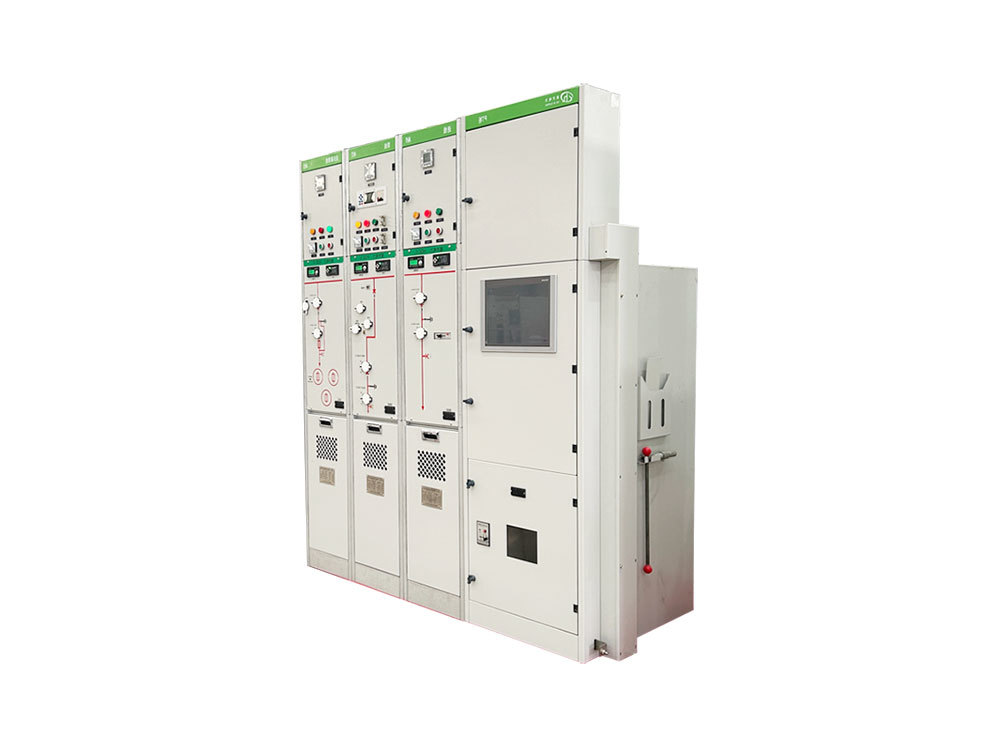
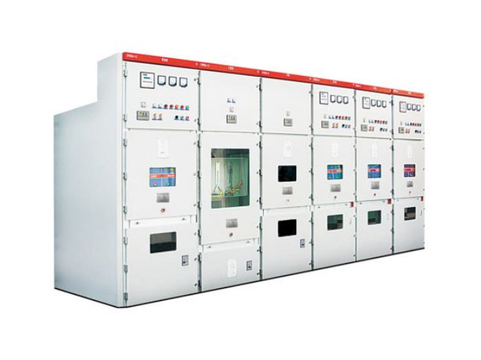
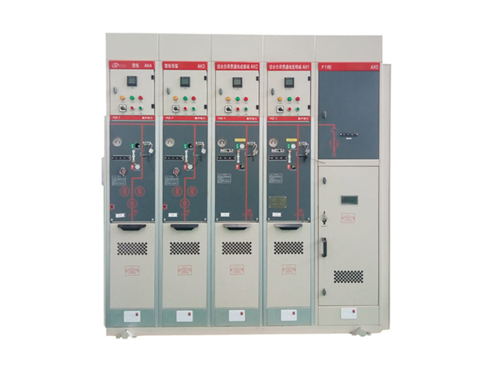
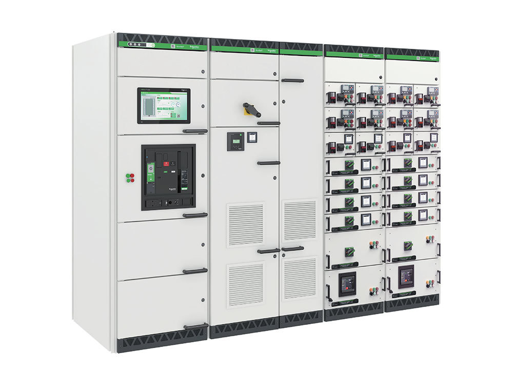
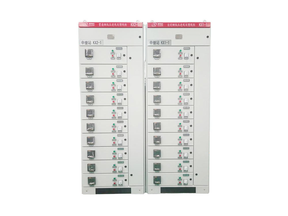
The HQGDF fixed-partition low-voltage switchgear is a new type of low-voltage complete switchgear with advanced domestic technology. It was developed by our company based on the requirements of the market and the special requirements and engineering applicability of user power distribution schemes, building upon our withdrawable switchgear.
This product is a fully type-tested, combination-type, multi-functional low-voltage switchgear that meets the GB7251.12-2013B standard. Its electrical and mechanical design uses modular principles. By selecting standard components and assemblies, it achieves compactness, diversity, and flexibility in cabinet assembly schemes. This product has earned widespread recognition and praise from domestic and international users due to its superior performance, excellent quality, and comprehensive service.
This product adopts an independent modular structure design, consisting of a horizontal busbar compartment, a vertical busbar compartment, a functional unit compartment, and a cable compartment. These compartments are separated and sealed using steel plates or insulating plates, effectively preventing interference between various accidents. In addition, with advanced internal components—primarily internationally renowned brands—the product boasts high breaking capacity, good sealing performance, reliable protection, and strong capabilities for interfacing with microcomputers. It is a new product suitable for power plants, substations, and various industrial and mining enterprises' AC power distribution systems.
● Compact design, accommodating more functional units within a smaller space.
● The basic frame of the device is a modular structure assembled from C-shaped open profiles, with a C-profile module unit E = 25mm.
● Separated into busbar compartments, cable compartments, and various functional unit compartments using galvanized thin steel plates and insulating plates.
● Flexible assembly into different structural forms as needed based on the scheme.
● All branch busbars and components are connected using hard copper bar connections.
Application Areas
This product is suitable for AC 50~60Hz, rated voltage 660V and below systems, and used for general control of power generation, power transmission, power conversion, and power consumption equipment. It can be used in all places requiring high-reliability low-voltage power supply systems, including distribution centers and power control centers. It can be widely applied in various fields, including industrial applications: metallurgy, papermaking, manufacturing, mining; construction: shopping malls, hotels; and infrastructure: water treatment, airports, and ports.
Operating Environment Conditions
1. Ambient Temperature
Short-term maximum temperature: +40℃
24-hour maximum average temperature: +35℃
Minimum temperature: -5℃
When the equipment is used at temperatures higher than those listed above, derating should be applied.
2. Environmental Conditions
Normal operating climate conditions follow the relevant provisions of the GB7251.12-2013 standard. Ambient relative humidity: 50% at 40℃. The conditions at indoor installation locations for the switchgear should meet the requirements of the corresponding standards. In situations where condensation may occur, ventilation or heating measures will be adopted inside the switchgear to prevent condensation. If the switchgear is installed at altitudes exceeding 2000 meters, derating of the equipment will be necessary.
Cabinet Structure
1. Cabinet Partitioning
The switchgear is divided into four compartments:
Horizontal busbar compartment: at the top of the cabinet
Functional unit compartment: at the front right of the cabinet Cable compartment: at the rear of the cabinet
Pressure relief channel: front of the busbar compartment
This product uses a 3b separation method, where the secondary component compartment and the cable and busbar connection compartment are all separated functional spaces. The primary component compartment is located at the front of the cabinet, the cable compartment at the rear, and the busbar compartment at the top and middle side of the cabinet. A professional heat dissipation and pressure relief channel is located in front of the busbar compartment. Each functional unit compartment is individually sealed; the horizontal busbar compartment is separated from the functional unit compartment and cable compartment by metal plates; the functional unit compartment and vertical busbar compartment and pressure relief channel are separated by metal plates or insulating plates. The partition between the functional unit compartment and pressure relief channel has a corresponding valve. When arcing occurs in the functional unit compartment, the valve opens, the pressure relief channel opens, and the arc is contained within the functional compartment or the location of the arc, ensuring that a fault in one unit does not spread to other units.
2. Busbar System
The switchgear main busbars are located at the top of the cabinet, and the distribution busbars (vertical busbars) are assembled in a closed vertical channel to prevent arc-induced discharge and prevent human contact.
The cabinet has an independent PE grounding system and N neutral conductor, both running through the entire device and installed at the bottom of the cabinet. Grounding or grounding of each circuit can be connected nearby. The frame structure is entirely riveted with self-tapping screws, providing high grounding reliability.
The neutral busbar and neutral protection busbar are installed parallel to the bottom of the functional unit compartment and vertically in the cable compartment. If the N line and PE line are separated by insulators, the N line and PE line are used separately; if they are short-circuited by a conductor, they become a PE/N line.
3. Protective Grounding System
The device's protection circuit consists of a separately installed PE line (or PEN line) running the entire length of the array and conductive structural components. The metal structural components in the device, except for the outer doors and sealing plates, are all galvanized. At the joints of the structural components, careful design ensures that they can carry a certain short-circuit current.
Main Electrical Parameters
Main Circuit Rated Voltage (V) | AC 380(400), 660 | |
Auxiliary Circuit Rated Voltage (V) | AC 220, 380(400), DC 110, 220 | |
Rated Frequency (Hz) | 50(60) | |
Rated Insulation Voltage (V) | 660(1000) | |
Rated Current (A) | Horizontal Busbar | ≤4000 |
Vertical Busbar (MCC) | 1000 | |
Busbar Rated Short-Time Withstand Current (KA/1s) | 50, 80 | |
Busbar Rated Peak Withstand Current (KA/0.1s) | 105, 176 | |
next page
previous page
next page
OTHER PRODUCTS
ONLINE MESSAGE
*Note: Please make sure to fill in the information accurately and maintain smooth communication. We will contact you as soon as possible


